The device requires nearly a minute to initialize. During this period, it can and often will output false detection signals. Circuit or controller logic needs to take this initialization period into consideration.
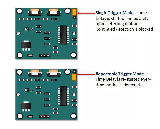
The trigger mode selection jumper allows you to select between single and repeatable triggers. The affect of this jumper setting is to determine when the time delay begins.
| SINGLE TRIGGER – The time delay begins immediately when motion is first detected. | |
| REPEATABLE TRIGGER – Each detected motion resets the time delay. Thus the time delay begins with the last motion detected. |
 This
motion sensor module uses the LHI778 Passive Infrared Sensor and the BISS0001 IC
to control how motion is detected.
This
motion sensor module uses the LHI778 Passive Infrared Sensor and the BISS0001 IC
to control how motion is detected.
The module features adjustable sensitivity that allows for a motion detection range from 3 meters to 7 meters.
The module also includes time delay adjustments and trigger selection that allow for fine tuning within your application.
This article discusses these various functions and demonstrates how to integrate them for use with your Arduino.
The HC-SR501 is readily available for several online sources.
eBay Amazon Bang
Good AliExpress
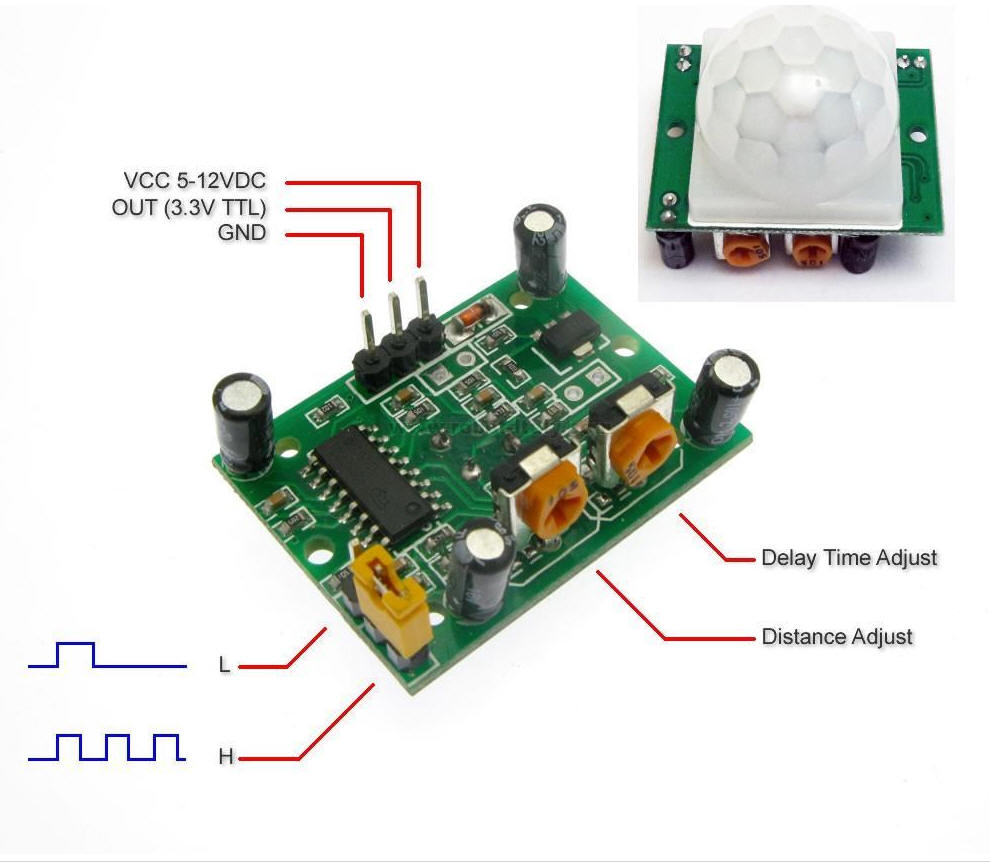
The pin-outs and controls for this device are shown in the picture below and described in the following table.

| Pin or Control | Function |
|---|---|
| Time Delay Adjust | Sets how long the output remains high after detecting motion.... Anywhere from 5 seconds to 5 minutes. |
| Sensitivity Adjust | Sets the detection range.... from 3 meters to 7 meters |
| Trigger Selection Jumper | Set for single or repeatable triggers. |
| Ground pin | Ground input |
| Output Pin | Low when no motion is detected.. High when motion is detected. High is 3.3V |
| Power Pin | 5 to 20 VDC Supply input |
The SR501 will detect infrared changes and if interpreted as motion, will set its output low. What is or is not interpreted as motion is largely dependent on user settings and adjustments.
The device requires nearly a minute to initialize. During this period, it can and often will output false detection signals. Circuit or controller logic needs to take this initialization period into consideration.
The device will detect motion inside a 110 degree cone with a range of 3 to 7 meters.

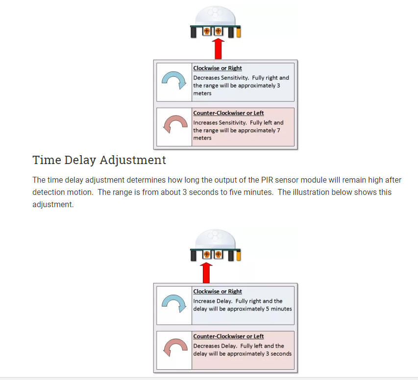
As mentioned, the adjustable range is from approximately 3 to 7 meters. The illustration below shows this adjustment. You may click to enlarge the illustration.
 Time
Delay Adjustment
Time
Delay AdjustmentThe time delay adjustment determines how long the output of the PIR sensor module will remain high after detection motion. The range is from about 3 seconds to five minutes. The illustration below shows this adjustment.

The output of this device will go LOW (or Off) for approximately 3 seconds AFTER the time delay completes. In other words, ALL motion detection is blocked during this three second period.
For Example:
Imagine you’re in the single trigger mode (see below) and your time delay is
set 5 seconds.
|
OVERRIDING THE TIME DELAY – If you’re connecting your HC-SR501 to an Arduino, it is likely that you are going to take some sort of action when motion is detected. For example, you may wish to brighten lights when motion is detected and dim the lights when motion is no longer connected
Simply delay dimming within your sketch.
The trigger mode selection jumper allows you to select between single and repeatable triggers. The affect of this jumper setting is to determine when the time delay begins.
| SINGLE TRIGGER – The time delay begins immediately when motion is first detected. | |
| REPEATABLE TRIGGER – Each detected motion resets the time delay. Thus the time delay begins with the last motion detected. |
Imagine that you want to control lighting on a dance floor based upon where the dancers are dancing. Understanding how the time delay and trigger mode interact will be necessary to controlling that lighting in the manner that you want.
In this first example, the time delay is set to three seconds and the trigger mode is set to single. As you can see in the illustration below, the motion is not always detected. In fact, there is a period of about six seconds where motion can not be detected. Feel free to click on the image to enlarge.

In the next example, the time delay is still at three seconds and the trigger is set to repeatable. In the illustration below, you can see that the time delay period is restarted. However, after that three seconds, detection will still be blocked for three seconds.
As I mentioned previously, you could override the 3 second blocking period with some creative code, but do give that consideration. Some of the electronics you use may not like an on and then off jolt. The three seconds allows for a little rest before starting back up.

This only requires three wires.

The sketch simply turns on Your Arduino LED connected to Pin 13 whenever motion is detected.
Be sure to beware of and somehow handle the 1 minute initialization in whatever application you develop.
//Henry's Bench
// HC-SR501 Motion Detector
// Sample Sketch
int ledPin = 13; // LED on Pin 13 of Arduino
int pirPin = 7; // Input for HC-S501
int pirValue; // Place to store read PIR Value
void setup() {
pinMode(ledPin, OUTPUT);
pinMode(pirPin, INPUT);
digitalWrite(ledPin, LOW);
}
void loop() {
pirValue = digitalRead(pirPin);
digitalWrite(ledPin, pirValue);
}